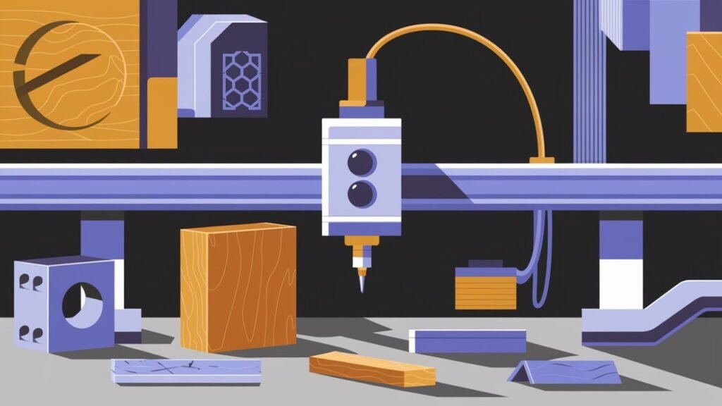
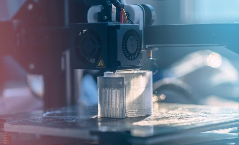
Micro-CNC machining is the technology behind many of the tiny, complex components we rely on every day—from the casing around your phone to small instruments used in hospitals. It might sound like a highly technical process, but it can be understood as a computer-guided carving system that works at an incredibly small scale. Rather than shaping large blocks of material, this method focuses on minute components where precision is the difference between success and failure.
Why exactly does size matter? As parts shrink, the room for error shrinks as well. A tiny deviation that would be harmless in a larger component can make a micro-part completely unusable. Micro-CNC machining eliminates most of that risk by automating the cutting, drilling, and shaping processes, allowing manufacturers to produce small parts quickly, reliably, and with very high consistency.
At its core, micro-CNC is a form of computer numerical control. The machine reads a digital set of instructions and translates them into precise physical movements. If traditional machining is like using standard tools to build furniture, micro-CNC is more like using a precision instrument to carve components that are barely visible to the naked eye. It performs work on materials such as metals, plastics, ceramics, and composites, with tolerances often down to 0.001 mm—roughly the width of a human hair in some cases.
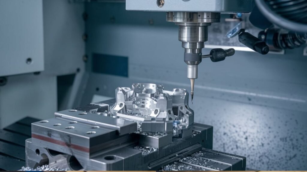
Working with such tiny features calls for the right equipment. Machine configurations vary—some are optimized for cutting, others for drilling, milling, or turning—and certain machines combine all these operations. The choice depends on the material, the geometry of the part, and the level of precision required. The machine itself does much of the heavy lifting, but the role of software is just as critical. CAD software is used to build the 3D model of the component, including every dimension and detail. CAM software then translates that model into G-code, a language the machine understands. In essence, CAD creates the blueprint, while CAM turns it into a recipe the machine can follow.
The manufacturing process follows a clear sequence. First, an engineer designs a complete 3D model of the part, specifying material, size, shape, and any special treatments needed. At this stage, they also decide how the part will be made, which tools are best, and whether it will require finishing after machining. Once the model is complete, CAM software converts it into G-code instructions. These instructions tell the machine when to move, where to cut, when to pause, and which tool to use.
Next comes setup. The material is placed securely on the machine bed, aligned carefully, and fitted with the necessary cutting bits or drills. The operator usually runs a test before the real job begins. Once everything is ready, the machine executes the program automatically, cutting, drilling, or shaping the material exactly as specified. Complex parts may require multiple passes or tool changes during the same run.
After machining, many parts still need finishing. Cleaning, polishing, removing sharp edges, applying coatings, or heat treating are common steps used to improve the surface or performance of the part. The final stage is inspection. Precision is the whole point, so every part must be verified. Micrometers, lasers, and other measuring tools check the size, shape, and surface quality. If something is off, the part may be re-machined or corrected.
Micro-CNC machining is used extensively in electronics, medical devices, aerospace, automotive, and even jewelry. It is the reason we can have smaller phones, safer implants, and lighter aircraft components. The ability to hold accuracy within 0.001 mm makes this process invaluable for industries where reliability depends on exact specifications.
The benefits go beyond precision. Because the process is automated, it reduces human error and lowers the chance of defects. It also cuts down on material waste, since the machine works with tightly controlled movements. This makes it both a quality and an efficiency advantage. For businesses that need high-performing parts in large or small volumes, micro-CNC offers a dependable path from concept to finished product.
One common question is what materials can be used. Aluminum, titanium, steel, ABS, PVC, ceramics, and composites are all compatible, depending on the application. Medical components often use plastics for their biocompatibility, while aerospace parts generally need stronger metals or composites. Another question is which industries benefit most. The answer includes every field where size, accuracy, and detail matter—from hearing aids to satellite components.
By taking a digital idea and turning it into a physical object with microscopic accuracy, micro-CNC machining has become a cornerstone of modern manufacturing. Whether you’re developing next-generation medical tools, electronic parts, or aerospace components, this technology offers the speed and precision needed to bring ambitious projects to life.