**Understanding the Geometry Shift**
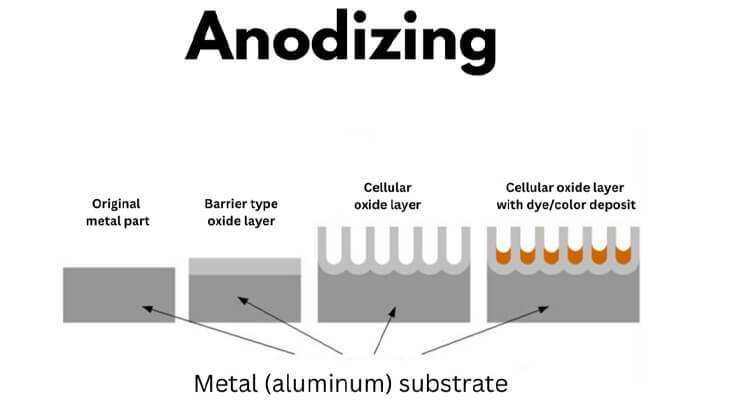
Unlike conventional surface coatings, anodization operates as a metallurgical conversion. When aluminum interacts with an electrolytic solution, the resulting oxide matrix develops simultaneously into the substrate and away from the original boundary. Manufacturing guidelines consistently recognize this dual expansion, indicating that approximately half of the final layer depth replaces existing metal while the remainder protrudes outward. Consequently, every treated component experiences measurable geometric alteration. Ignoring these predictable shifts frequently results in rejected assemblies, particularly when clearance fits or interference joints are involved.
**How Coating Variants Influence Tolerances**
The severity of dimensional deviation directly correlates with the selected anodize specification. Heavy-duty Type III hardcoats typically range from 25 to 75 microns, generating substantial material displacement. A standard 50-micron application can expand external profiles by roughly 25 microns per face while constricting internal cavities by an equivalent amount, potentially locking rotating assemblies or binding linear guides. Conversely, decorative Type II finishes span 5 to 25 microns, producing shifts that rarely disrupt standard commercial tolerances. For aerospace and fatigue-sensitive applications, Type I chromic acid treatments remain the preferred choice. Measuring merely 0.5 to 2.5 microns, this variant introduces negligible size changes and preserves structural integrity without compromising corrosion resistance entirely.
**Strategic Machining and Feature Protection**
Proactive design adjustments prevent costly rework. Engineers typically address anticipated growth by machining external surfaces slightly below target dimensions while leaving internal holes and threaded inserts oversized. Once the protective layer forms, final machining or reaming restores the component to its exact specifications. Alternatively, masking sensitive zones with high-temperature tape or chemical resins preserves bare aluminum on electrical contacts, press-fit interfaces, and grounding points. When thread engagement remains uncompromised, operators often defer tapping operations until after the finishing stage. Automated design-for-manufacturability analysis routinely flags tolerance conflicts before production begins, ensuring alignment between CAD models and physical outcomes.
**Crafting Unambiguous Engineering Callouts**
Clear documentation eliminates guesswork on the shop floor. Every anodized component should specify the coating classification, visual grade, exact thickness with allowable variance, and measurement timing. A robust specification might read: “Anodize per MIL-A-8625, Type III, Class 2, 0.002 ± 0.0005 inches, dimensions verified post-finish.” Explicitly stating whether measurements apply before or after coating directs machinists to apply correct offsets and empowers inspectors to validate against the proper baseline. Additionally, material selection influences coating uniformity; copper-rich alloys like the 2000 series yield thinner, less consistent layers compared to silicon-modified counterparts. Always verify achievable thickness parameters with your finishing partner prior to finalizing designs.