Automotive component projects rarely allow a slow, linear path. Engineers must meet tight deadlines while ensuring that each bracket, mount, panel, or housing performs exactly as intended. Sheet metal prototyping gives teams a practical way to move through that pressure: build physical parts early, test them, learn from them, and revise quickly. Instead of committing to expensive hard tooling before the design is proven, manufacturers can use fabricated metal prototypes to explore form, fit, and function with far less risk.
The main advantage is rapid iteration. Suspension mounts, engine brackets, and other complex components often need several rounds of adjustment before they are production-ready. Fast prototype cycles let designers resolve questions about clearances, mounting points, load paths, and assembly sequence while there is still time to change the design. This early refinement improves functionality, durability, and appearance, and it helps prevent defects from reaching mass production. Catching problems during prototyping is far cheaper than correcting them after tooling has been cut or vehicles have been assembled.
A structured prototyping workflow keeps the project moving. It usually starts with requirements and concept sketches, then moves into CAD modeling and design-for-manufacturability review. Next, engineers select material grade and thickness, choose cutting and forming methods, and define bends, holes, tabs, and joining details. The first physical prototype is cut, bent, joined, and finished, then inspected and tested. Results feed back into the CAD model, and the cycle repeats. One often overlooked practice is documenting why each change was made; after several iterations, that record prevents teams from repeating old mistakes or undoing earlier improvements.
Sheet metal fabrication is versatile, but it is especially valuable for automotive parts such as suspension brackets, engine mounts, body panels, dashboard structures, clips, connectors, and small enclosures. These components often need a strong strength-to-weight ratio, repeatable geometry, and the ability to be produced in volume. Prototyping helps confirm that the chosen design can meet those demands before production tooling is finalized.
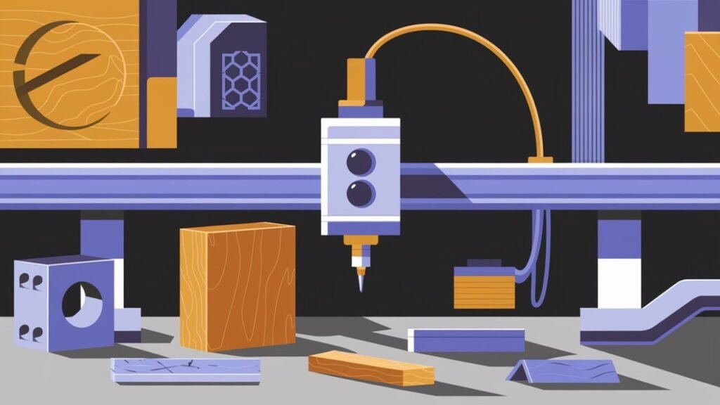
The right toolset makes prototyping faster and more reliable. CAD and CAE software allow engineers to simulate stress, stiffness, and deformation before metal is cut. Cutting equipment such as laser, plasma, waterjet, or CNC routers creates blanks and features. Press brakes form bends; welding, riveting, or fastening joins parts; and inspection tools verify dimensions. A press brake, for example, can bend sheet metal up to 120 degrees with accuracy as fine as 0.1 mm, which is why bend sequencing and tooling choices matter so much. 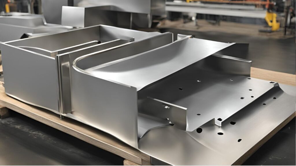 Digital prototyping is equally important. SolidWorks, Fusion 360, ANSYS Sheet Metal, and similar platforms help teams visualize and optimize designs virtually. Using simulation early reduces the chance of costly revisions later, especially when tolerances, springback, or complex geometry are involved.
Sustainability is becoming a bigger priority in automotive manufacturing, and prototyping can support greener practices. Optimized nesting and blank layout reduce scrap. Fewer physical iterations mean less material and energy consumed. Recyclable metals such as aluminum and steel can be recovered, and lightweight prototypes help validate designs that improve fuel efficiency or electric vehicle range. In this way, prototyping is not only a design tool; it can also support long-term environmental goals.
Testing the prototype is as important as building it. Common evaluation methods include dimensional inspection, fixture and assembly checks, functional load tests, fatigue cycling, corrosion exposure, and environmental testing. The more closely the test setup mimics real-world use, the more useful the results will be. Teams should document test conditions, failures, and measured performance so that each revision is based on evidence rather than guesswork.
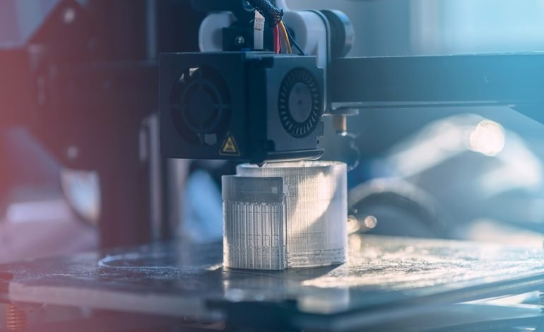
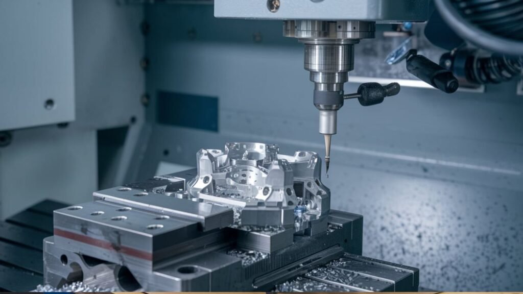
The field is changing quickly. Automation, robotics, digital twins, advanced simulation, and tighter laser cutting tolerances are making prototyping faster and more precise. Some advanced laser cutters can hold tolerances as tight as ±0.005 inches, which supports complex curves, folds, and perforations. Modern equipment may require investment, but it can improve accuracy and shorten lead times. Compared with other prototyping routes, sheet metal fabrication is often efficient for thin, durable, formed parts, while 3D printing may suit plastic or highly organic shapes and CNC machining may fit solid, high-precision components. The best method depends on material, geometry, volume, and testing needs.
If prototyping is outsourced, choose a partner carefully. The best suppliers offer end-to-end services such as cutting, bending, welding, finishing, and inspection, which avoids delays caused by coordinating multiple vendors. Share clear CAD files, tolerances, material specifications, and expected use conditions. Ask for design-for-manufacturing feedback before production begins. Be cautious of partners that promise unrealistically short timelines or dramatically lower costs; those offers can hide compromises in quality, traceability, or dimensional accuracy.
Every prototype project has hiccups. Springback, material thickness variation, tool wear, holes placed too close to bends, welding distortion, and tolerance stack-up are common. Good countermeasures include designing to known bend radii, using compensation in the CAD model, checking flat patterns, building fixtures for repeatability, and inspecting critical features after each operation. When moving from a single prototype to multiple iterations or a small batch, consistency becomes the next challenge. Standardizing materials, using the same tooling setup, automating repetitive steps like laser cutting or bending, and applying in-process checks can reduce variation. Modular designs also help: breaking a component into smaller interchangeable sections makes updates, repairs, and customization easier. Dashboards, for example, can use modular sheet metal panels that are swapped or revised without redesigning the entire structure.
Speed can be gained in several ways. Run simulation and material selection in parallel, get early DFM feedback, use standard fasteners and bend radii, avoid unnecessary cosmetic requirements, and work with a supplier that can handle cutting, forming, and finishing under one roof. Integrating prototyping into the broader product development workflow is equally important. Version control, PLM or CAD data management, test data feedback, and alignment between prototype tolerances and production tolerances all help ensure that each iteration moves closer to a manufacturable design.
Safety must never be an afterthought. Sheet metal edges are sharp, press brakes and lasers are powerful, and welding creates fumes and heat. Wear appropriate PPE, use machine guards, follow lockout procedures, keep work areas clear, and train operators on each process. Proper safety protocols protect people and also improve consistency because controlled processes are easier to repeat.
Automotive engineers are also pursuing lighter vehicles to improve efficiency and performance. Prototyping with aluminum, high-strength steel, and other lightweight materials helps validate whether a component can meet strength and weight targets. As designs include more complex curves, folds, and perforations, accuracy becomes critical. Laser cutting, CNC forming, simulation compensation, and careful fixture design help maintain precision. Looking ahead, prototyping will continue to become faster, more accurate, and more flexible as digital tools, automation, and sustainable materials advance.
In short, sheet metal prototyping is an invaluable method for developing automotive components. It lets teams test, iterate, and improve faster while controlling cost and resource use. From small brackets to large body panels, the applications are broad. By following a structured process, using simulation wisely, testing under realistic conditions, and partnering with the right fabricator, engineers can turn rough concepts into production-ready designs with confidence.
Frequently asked questions:
What industries use sheet metal prototyping? It is widely used in automotive and aerospace, but also in electronics for enclosures, construction for structural elements, and consumer goods for functional or decorative components. Its adaptability makes it useful across many sectors.
Can prototypes use multiple sheet metal materials? Yes. A prototype can combine aluminum for lightweight properties with steel for durability, allowing engineers to evaluate different characteristics in one design and optimize the final specification.
How precise are sheet metal prototypes? Precision depends on the equipment, but tolerances as tight as ±0.1 mm are common. Advanced CNC machines and laser cutters can achieve even finer accuracy for complex geometries, which is essential for functional testing and performance evaluation.
Is sheet metal prototyping suitable for small parts? Absolutely. It excels at producing small, intricate items such as brackets, clips, and connectors. As long as the design follows manufacturability guidelines, even tiny components can be prototyped efficiently.
What is the typical cost of a sheet metal prototype? Cost varies by size, material, and complexity. Simple prototypes may cost a few hundred dollars, while larger or more intricate versions can reach several thousand. Compared with traditional manufacturing, prototyping is often a cost-effective investment.