Wire EDM utilizes electro-erosion principles to remove material without mechanical contact. A continuous brass wire, typically 0.1–0.3 mm in diameter, traverses the workpiece within a dielectric bath of deionized water while pulsed voltage generates micro-sparks across a 0.01–0.05 mm gap. Each discharge vaporizes microscopic volumes of metal, ensuring the wire never touches the substrate. This zero-cutting-force mechanism allows the processing of any electrically conductive material regardless of hardness, facilitating the machining of tungsten carbide, polycrystalline diamond, and tool steels heat-treated to HRC 70.
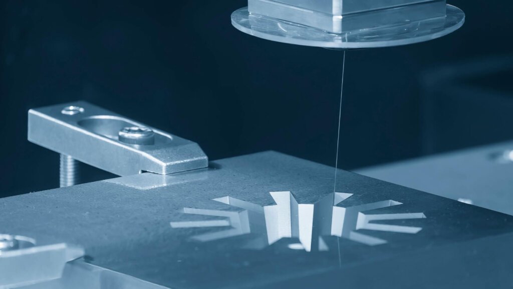
For design specifications demanding internal corner radii of 0.1 mm or keyway slots in hardened H13 steel, Wire EDM is frequently the only practical solution. Conventional CNC milling is geometrically constrained by end mill radius, limiting minimum internal corners to 0.25–0.5 mm. Wire EDM resolution depends solely on wire diameter, permitting sharper transitions essential for precision tooling, aerospace load-path brackets, and micro-instrumentation. Recommended workflow dictates rough-machining components in a soft, annealed condition, applying thermal treatment, and finishing critical features via EDM to neutralize post-heat-treat distortion.
Economic models for Wire EDM contrast sharply with CNC operations. The absence of tool wear and minimal setup forces simplifies cost structures, though cycle times remain slower, averaging 2–6 mm/min per pass on thick stacks. Hourly rates vary by region, generally spanning $15–$35/hr in ISO-certified Asian facilities and $40–$120/hr in the US. Per-part costs scale with cumulative cut length and pass requirements, typically ranging from $30 to over $500. High-precision execution requires management of the recast layer, a resolidified surface zone 2–15 µm thick. Fatigue-critical aerospace components and medical implants necessitate recast layers below 2 µm, achieved through multiple finish skims or electrochemical polishing, while general tooling may tolerate thicker layers.
Dimensional accuracy reaches ±0.002–0.005 mm with surface finishes of Ra 0.1–0.4 µm using rough-plus-skim strategies, approaching grinding quality on complex contours. Single-pass roughing yields ±0.010–0.020 mm. Wire EDM excels for delicate structures, including walls thinner than 0.3 mm and cantilevered features prone to deflection under milling loads. Through-profile operations such as gears, sprockets, and apertures are efficiently executed in single passes regardless of stock thickness. Material selection must ensure electrical conductivity; non-conductive plastics, ceramics, and glass are incompatible, while carbon-fiber reinforced polymers (CFRP) present matrix inconsistencies that favor CNC alternatives.
XC Machining integrates Wire EDM with CNC, injection molding, and sheet metal fabrication, leveraging Fanuc and Makino systems for ±0.003 mm positioning accuracy. Our engineering team supports complex projects across aerospace, medical, and industrial sectors. Submit technical drawings for a complimentary DFM review at xcmachining.com to evaluate design feasibility and optimize manufacturing efficiency.