Turning a sketch into a solid metal component can feel almost magical, especially when a finished part appears in a matter of days. In reality, the process is driven by a combination of digital design, precision equipment, and practical engineering. Metal prototype machining gives product teams a way to test real dimensions, strength, and fit before committing to expensive production tooling.
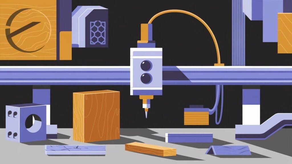
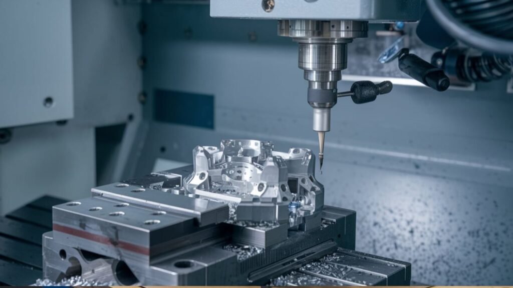
At its core, metal prototype machining is a subtractive manufacturing method. A solid block of metal, often called a blank, is cut, drilled, milled, or turned until it matches the intended design. Unlike mass production, the priority is not thousands of identical units. Instead, the goal is speed, flexibility, and the ability to produce one or a few parts for evaluation. For example, before manufacturing a new bicycle bracket, an engineer can machine a single aluminum version, install it, and see whether it performs as expected.
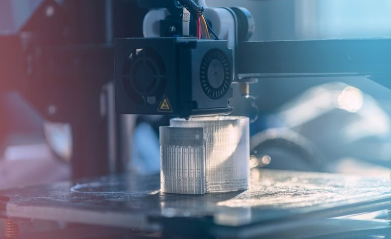
The rise of rapid prototyping began in the late 1980s, when early 3D printing methods such as stereolithography first attracted attention. However, plastic models could not always replicate the strength, heat resistance, or mechanical behavior of metal. As computer-controlled machining improved, CNC metal prototyping became a faster and more reliable way to create functional parts. Today, even small workshops and independent designers can access desktop CNC machines or online machining services. Advanced multi-axis systems and hybrid workflows that combine additive manufacturing with CNC cutting have made it easier than ever to produce complex metal prototypes efficiently.
A typical metal prototype machining project starts with a detailed 3D model created in CAD software. This digital file defines every hole, surface, radius, and critical dimension. CAM software then translates the model into machining instructions, selecting toolpaths, cutting speeds, and tool changes. Depending on the geometry, the part may be produced on a CNC mill, lathe, or multi-axis machining center. After machining, the part may be deburred, sanded, bead blasted, or otherwise finished to improve appearance and usability. Testing follows, and if the part fails or needs improvement, the design can be revised and machined again.
Material selection plays a major role in the outcome. Aluminum is a popular choice because it is relatively lightweight, easy to machine, and cost-effective for early prototypes. Steel offers greater strength and durability, though it may require longer machining time. Titanium is valued in aerospace, medical, and high-performance applications because of its excellent strength-to-weight ratio and corrosion resistance, but it is usually more expensive and more challenging to cut. Choosing the right metal depends on the part’s function, budget, required tolerances, and testing conditions.
Designing for metal prototype machining also requires practical considerations. Overly complex shapes may increase machining time and cost, especially during early concept validation. Thin walls can vibrate, warp, or break, so maintaining adequate thickness is important. Sharp internal corners are difficult to cut cleanly and can create stress points, while rounded corners and fillets help improve both manufacturability and part strength. Designers should also think about how the part will be held during machining, since proper fixturing prevents movement and improves accuracy.
Once a prototype proves its form, fit, and function, teams often face the next decision: how to move toward production. In some cases, machined prototypes can become final parts, especially in low-volume industries where complexity matters more than high output. In other cases, bridge production offers a middle ground. This approach allows a small batch of metal parts to be manufactured before investing in molds, casting tools, or large-scale production equipment. It is especially useful when design details still need final validation or when market demand is not yet certain.
Cost, accuracy, and software are common concerns for beginners. Machining costs depend on material, part complexity, machine time, and required finish. While titanium parts may cost more than aluminum ones, machining is often more economical than creating custom molds for a small number of prototypes. With the right setup, tight tolerances are achievable, sometimes within ±0.005 inches or better. Popular CAD tools such as SolidWorks, Fusion 360, and Inventor help designers create models, while CAM platforms generate the instructions that guide CNC machines. For parts with difficult internal channels, teams may combine machining with additive manufacturing or use specialized multi-axis setups.
Metal prototype machining has changed the way products are developed. It reduces guesswork, shortens design cycles, and allows teams to test real metal components under real conditions. Whether the goal is a custom drone bracket, an automotive part, a medical device component, or an industrial fixture, CNC prototyping provides a practical path from idea to functional hardware. With thoughtful design and the right manufacturing approach, a strong, accurate metal prototype can be ready long before the competition finishes refining its drawings.