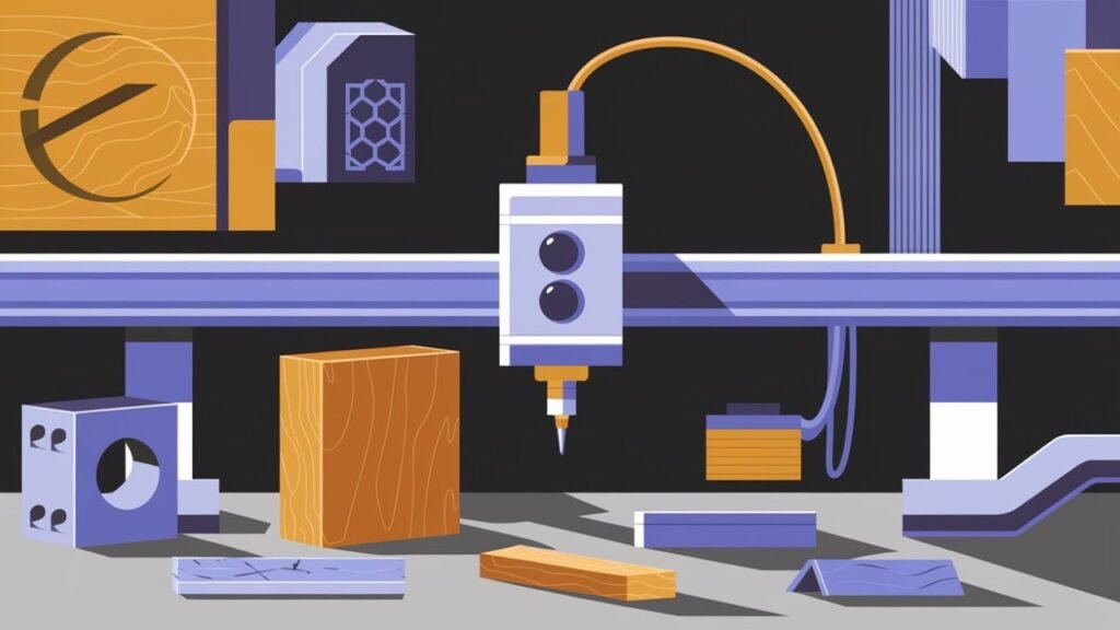
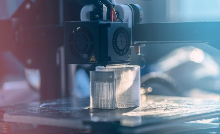
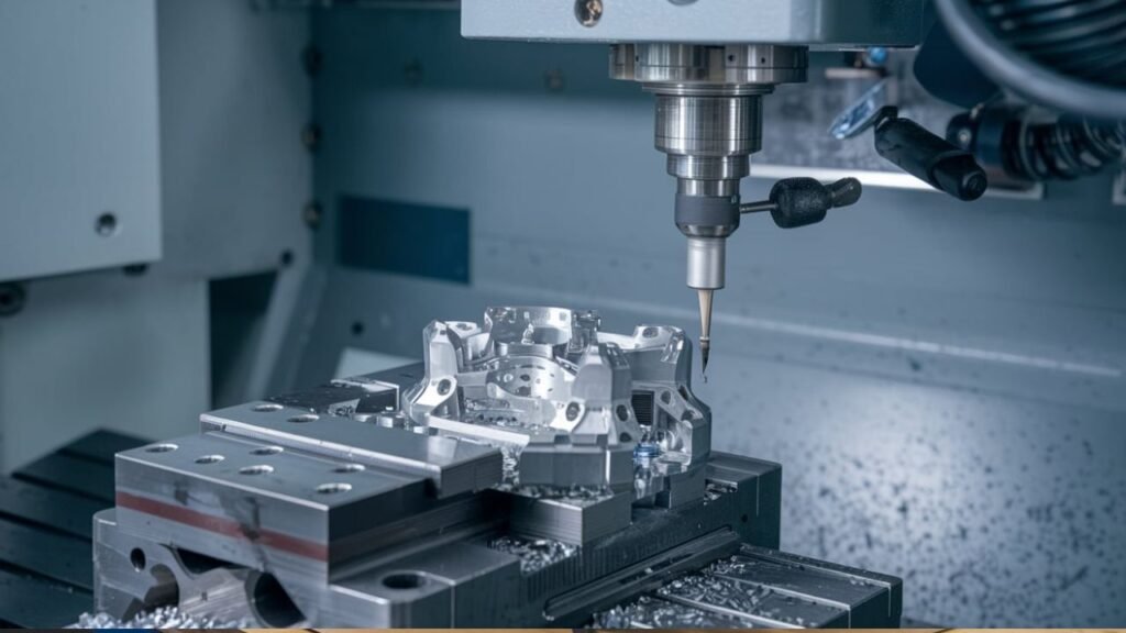
Milling machines remain one of the most important tools in modern manufacturing, helping producers turn raw material into precise parts for everything from consumer products to advanced industrial systems. Their ability to combine repeatability, accuracy, and flexibility has made them essential in factories where dimensional control and surface quality directly affect performance.
At its core, milling is a material-removal process in which a rotating cutting tool shapes a stationary workpiece. The operation can produce flat faces, slots, pockets, threads, and complex three-dimensional contours, often with tight tolerances. Because the cutting action can be controlled by programmed motion paths, milling supports both simple production work and highly detailed component manufacturing.
The modern era of milling is closely tied to the early nineteenth century, when Eli Whitney introduced a milling machine in New Haven, Connecticut in 1818. That development helped move manufacturing away from purely hand-guided methods and toward more standardized, efficient production. Over time, mechanical milling evolved into CNC-based systems that can execute intricate tool paths with minimal human intervention.
A well-designed milling machine depends on a group of coordinated components. The base provides the rigid foundation that supports the entire structure and helps maintain stability under cutting forces. The knee assembly enables vertical positioning, while the saddle allows controlled cross travel, giving the machine the precision needed for accurate part geometry. Together with the spindle, worktable, and control system, these elements form the operational core of the machine.
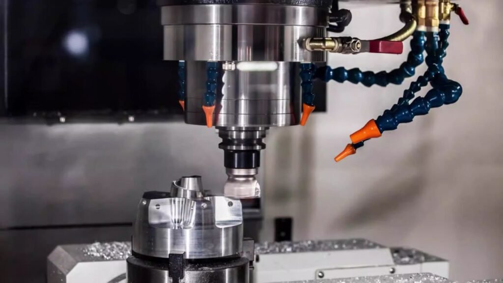
Milling machines are commonly classified by spindle orientation and axis configuration. Vertical milling machines have a spindle aligned perpendicular to the worktable, making them well suited for face milling, drilling, and precision hole work. Horizontal milling machines place the spindle parallel to the table, which is often advantageous for heavier cuts, side milling, and gang milling operations where multiple tools or longer engagements are required.
Axis count also defines the machine’s capability. A 3-axis machine moves along the X, Y, and Z axes and is the standard platform for many general machining tasks. A 4-axis machine adds a rotary axis, allowing better access to cylindrical and contoured surfaces. A 5-axis machine introduces additional rotary motion, enabling complex shapes to be machined from multiple angles in a single setup. This can reduce fixturing time and improve accuracy, though it also demands more advanced programming and setup knowledge.
These capabilities explain why milling is so widely used across industries. In automotive manufacturing, milling supports both prototype development and high-volume production, where components must meet strict dimensional requirements while still being produced efficiently. Aerospace applications place even greater emphasis on precision and reliability, especially when machining critical flight components that must perform safely under demanding conditions. Medical manufacturing also relies heavily on milling, particularly for implants and specialized equipment made from difficult-to-machine materials and intricate geometries.
Operational success also depends on proper machine care and process selection. Daily removal of chips and coolant, regular lubrication of moving parts, and periodic inspection of cutting tools and alignments help maintain accuracy and extend machine life. When deciding between manual and CNC milling, manufacturers should consider part complexity, production volume, and required consistency. CNC milling is usually the stronger choice for repeatable, high-volume, or complex work, even though it involves a larger upfront investment. Manual milling can still be practical for one-off jobs or simpler tasks.
Machining parameters must also be matched to the job. The workpiece material, cutting tool material, and depth of cut are primary factors in selecting speed and feed. Harder materials generally call for slower cutting speeds, while tool diameter and flute count strongly influence the appropriate feed rate. Getting these settings right helps protect the tool, improve surface finish, and maintain dimensional stability.
As manufacturing continues to move toward tighter tolerances, more complex designs, and faster production cycles, milling technology keeps advancing. Understanding the strengths and limits of different machine types, from basic vertical setups to advanced 5-axis CNC systems, is essential for choosing the right approach. Used correctly, milling provides a dependable foundation for producing precision parts across a wide range of modern industries.